Difference between revisions of "PgFocus"
(→Optics) |
|||
| Line 146: | Line 146: | ||
[https://oshpark.com/shared_projects/d5IfqVyJ TSL1401CL-Adapter] | [https://oshpark.com/shared_projects/d5IfqVyJ TSL1401CL-Adapter] | ||
| + | |||
| + | |||
| + | == Bootloader == | ||
| + | |||
| + | pgFocus uses the Leonardo Boot loader, which can be uploaded via an AVR programmer listed below. | ||
| + | |||
| + | You can use the Arduino IDE to communicate with pfFocus and run simple Ardunio sketches to test basic communications. | ||
| + | |||
| + | Once you have confirmed that a Leonardo bootloader has been installed, then you can install the firmware. | ||
== Firmware == | == Firmware == | ||
Revision as of 19:56, 9 August 2018
Mailing List
All discussions and questions should be sent to the pgFocus mailing list at here
You can visit the pgFocus Google Group.
I am always interested in helping people implement pgFocus, I encouraged you to join the pgFocus Google Group/Mailing List.
Description
Since pgFocus was just released, documentation and the design is rapidly changing.
pgFocus is an open source and open hardware, for noncommercial use, focus stabilization device developed by Karl Bellvé at the Biomedical Imaging Group (Progam in Molecular Medicine, University of Massachusetts Medical School).
The pg in pgFocus is short for "Pretty Good". pgFocus isn't "Perfect", or "Definite" but it is pretty good! (inside the industry joke)
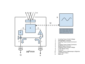
pgFocus monitors focus changes through the positional changes of a reflected laser beam. A significant feature of pgFocus is it acts as a "man-in-the-middle." It is designed to pass through faster high fidelity signals meant for a piezo Z controller while adding a slower focus control signal. This happens in the analog realm, which avoids sampling artifacts introduced by digitizing the original signal. This design also reduces the cost of pgFocus.
The following table is information I have gleaned from brochures and the web. It is as correct as I can make it. It a comparison between pgFocus and commercial focus stability systems from major manufacturers.
| pgFocus | Definite Focus | Perfect Focus | Ultimate Focus | CRISP | |
| Response Time | 30ms | NA | “milliseconds” | 200ms | NA |
| Stability Error (depth of focus) | >3% | NA | 33% | 12.5% | 5% |
| 3D Capable | Yes | No | No | No | No |
| Analog pass-through for Piezo Control | Yes | No | No | No | No |
| Open Hardware | Yes | No | No | No | No |
| Open Software | Yes | No | No | No | No |
External Implementations
Hardware
pgFocus uses the same Atmel ATMEGA 32U4 as seen in the Arduino Leonardo.
pgFocus is connected to a computer via a USB port. USB is used to power and to communicate with pgFocus.
Power
pgFocus uses the USB +5V power to generate +12V and -12V power using a standard DC to DC converter.
Digital to Analog Converter
pgFocus uses a ±5V 14bit DAC to modify incoming piezo Z signal. This is the upper and lower voltage limit that can be used to adjust the piezo Z signal. The DAC has a resolution of 0.6 mV. Based on our piezo Z controller (10µM/Volt), this works out to a minimum 6 nM step size at the objective.
Analog to Digital Converter
pgFocus uses a ±10V 14bit ADC to sample the incoming piezo Z signal. This is to allow pgFocus to automatically adjust the focus set point, without user intervention. This feature enables pgFocus to have automated 3D focus correction.
The incoming piezo signal is sampled and multiplied by 2. This effectively makes the ±10V ADC become a ±5V ADC, matching the ±5V DAC.
When pgFocus samples the incoming piezo Z signal, it rounds off the results to the nearest 50nM step since most people move their objectives at 50, 100 or 250nm increments. This allows the adjustment of the focus set point to be more accurately predicted because it is based on the distance from the original focus set point rather than just a new offset.
The gain of the ADC needs to be determined. I use a voltage protocol that measures two points; -1 Volt and 1 Volt.
((2/10) * 2^14) / ((abs(-1 Volt) + (1 Volt)) = gain.
Linear Light Array
The Linear Light Array represents a physical limit. The return beam must fall within its 128 pixels. The length of the 128 pixels is about 8mm. In our setup, the 8mm length of the Linear Light Array is equivalent to about 25 to 30µM range with a 60X objective. Longer Linear Light Arrays maybe used in future versions of pgFocus.
The Linear Light Array's location on the PCB is in the exact vertical center of the board. This allows you to put pgFocus in either vertical orientation and still use the same case.
We also use a High Pass Filter in front of the Linear Light Array that can be purchased from Peau Productions
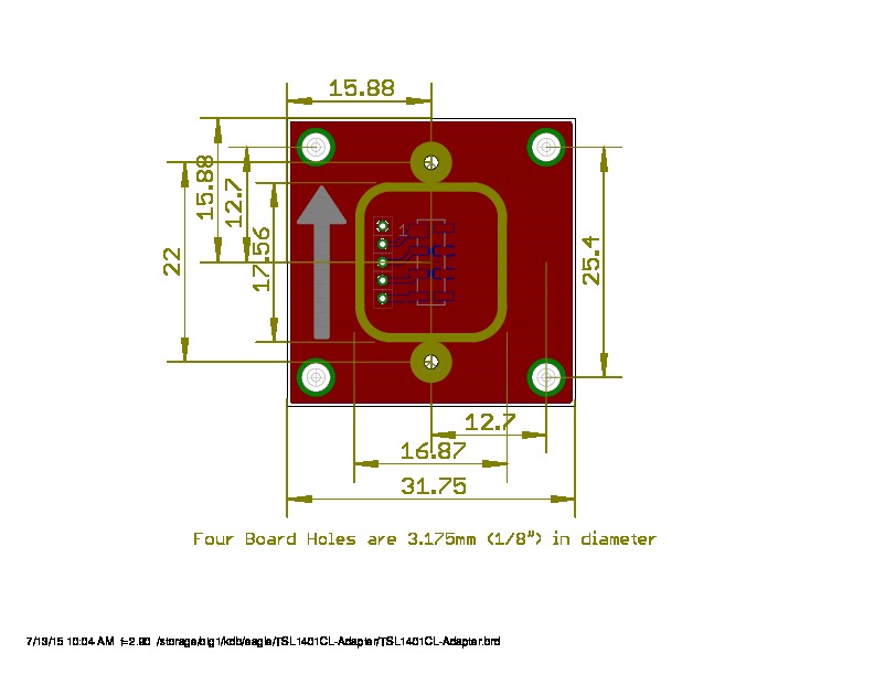
The Linear Light Array uses a custom 1.25" square PCB, with 4 0.125" (1/8") holes at each corner, 1" apart. Those holes can be used for mounting the sensor. All distances for the board below are in millimeters.
Digital Expansion Port
pgFocus makes accessible 8 digital I/O pins compatible with D0 to D7 pins on the Arduino Leonardo. These pins can be used for other light sensors, or perhaps a hardware switch to turn on/off focus, or to move the focus set point up or down.
+5V and ground lines are also made available. However, since USB is powering pgFocus, power maybe limited. Future versions of pgFocus might have a 5V DC jack if power is a limitation in the current design.
Optics
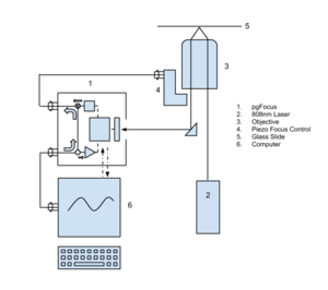
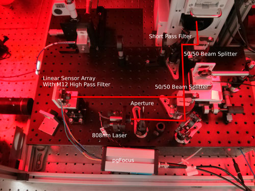
pgFocus uses a laser beam that is reflected off the cover glass/water interface to monitor the microscope focus. Hence, an objective with an NA of at least 1.45 is required. The laser beam wavelength should be different from that being used for science (1 mWatt, 808nm is a good choice) and must be coaligned with the TIRF beam. This can be done using a mirror, beam splitter and a short pass filter. Care must be taken to ensure that the fluorescence filter cube and other microscope optics will allow the return of the pgFocus beam back along its input path and back to the pgFocus detector and that the microscope optics will NOT allow the laser light to pass into the user's eyes or to reach the camera. Once the position and angle of the pgFocus beam is coincident with that of the TIRF beam a strong return pgFocus beam will be seen that moves with changes in microscope focus. The pgFocus detector array can now be aligned and centered on the beam.
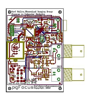
Eagle Files
Warning: PCB design has not been verified yet and may not be final.
OSH Park
Bootloader
pgFocus uses the Leonardo Boot loader, which can be uploaded via an AVR programmer listed below.
You can use the Arduino IDE to communicate with pfFocus and run simple Ardunio sketches to test basic communications.
Once you have confirmed that a Leonardo bootloader has been installed, then you can install the firmware.
Firmware
Firmware can now be found on github here: https://github.com/kbellve/pgFocus-firmware
Latest version of firmware is at version 0.9 and it is compatible with uManager
To update your firmware, please use an AVR programmer from Adafruit or Sparkfun .
If using a USB Tiny, use the following command:
avrdude -patmega32u4 -cusbtiny -Uflash:w:pgFocus_firmware-0.8.hex:i
Software
Software Installation
You can run the pgFocus hardware three different ways: Serial Commands, pgFocus Application, and µManager. All can be installed at the same time, but you can only run one of them at a time.
Serial Commands
The simplest way is to just use a terminal, or the Arduino IDE serial window. PgFocus uses 57600,8N1. PgFocus will respond to simple characters and commands:
- c
- Active calibration
- d
- Move focus down
- e
- Turn off auto exposure
- E
- Turn on auto exposure
- f
- Turn off/on focus control
- i
- Identify what we are
- l
- Light Profile
- s
- Stop Everything
- t
- Voltage Test which ramps voltage up and down
- v
- Verbose mode, but print stats
- x
- Load settings from flash memory
- y
- Save settings to flash memory
- voltage [±5 Volts]
- Sets the voltage or prints the voltage
- version
- Prints the firmware version
- offset [0 <-> 127]
- Sets or prints the focus offset
- slope
- Prints the slope of the linear regression performed during calibration
- step [0 <-> 1.5]
- Sets or prints the step size of the focus correction
- drift
- Prints the drift, or the distance from the focus set point
- mpv [10]
- Sets or prints the microns per volt of the piezo amplifier and controller.
- exposure [10000]
- Sets or prints the exposure time, in nanoseconds
- gain [1]
- Sets or prints the gain of the ADC
- intercept
- Prints the intercept of the linear regression performed during calibration
- residuals
- Prints the residuals of the linear regression performed during calibration
pgFocus application
There is the pgFocus standalone application that is written in the Processing language. The pgFocus standalone application can be found here: pgFocus-Software. You might also need to download the Arduino software for USB driver support.
µManager
Or you can run it through µManager. There is a pgFocus plugin and Device Adapter that is part of the normal µManager distribution. Just add pgFocus through µManager's Hardware Wizard, which should automatically detect it.
Description
After the Arduino Leonardo was released, pgFocus was redesigned to take advantage of the bootloader and pin layout for the Arduino Leonardo. If you can write an Arduino sketch, you can modify the source code to pgFocus!
pgFocus software reports the following:
- Light profile as seen by the Linear Light Array.
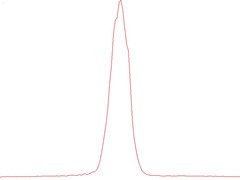
- Use this to align the physical position of pgFocus with respect to the return laser beam.
- Current centroid location of the light profile as seen by the Linear Light Array.
- Microscope stability based on the running Standard Deviation(converted to nM movement at the objective).
- Digital to Analog converter voltage output need to maintain current focus position.
- Calibration mode result.
pgFocus software can do the following:
- Lock focus at the current position.
- Move focus up by a specified amount (currently set to +50nM).
- Move focus down by a specified amount (currently set to -50nM).
pgFocus software has not be released yet since it was designed for the prototype version of pgFocus rather than this version. It will be released as soon as possible.
Linear Light Array Profile
pgFocus will show a continually updating profile of the return laser beam. The return laser beam needs to be centered vertically and horizontally on the Linear Light Array. This alignment needs to be performed while the microscope is in its normal mode of operation. If the microscope is heated in an environmental chamber, then it needs to be heated before this alignment should be performed.
A centroid calculation is performed on the Linear Light Array profile to get focus location. This calculation will only be performed by pgFocus if it detects a peak in the profile.
Calibration Mode
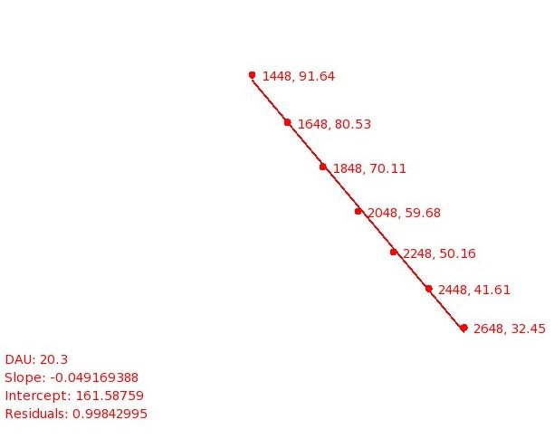
pgFocus needs to understand the relationship between the movement of the laser beam return signal seen on the Linear Light Array and the movement of the objective. This depends upon the location of pgFocus in relation to the objective. To determine this relationship, pgFocus has a calibration mode that moves the objective up and then down, while reading the position of the return laser beam. This information is plotted and a linear regression analysis is performed to determine the slope. The slope is the scale factor that pgFocus uses for calculations and for focus adjustments.
A calibration must be performed after first installing pgFocus, or if the distance between pgFocus or the objective changes (i.e. pgFocus is moved).
The user just needs to make sure the the return laser beam is aligned and centered on the Linear Light Array. pgFocus will take care of the rest and will store the resulting calculation in its EPROM.
Instructions on calibration can be found here: pgFocus_Calibration
The figure below is captured from the first prototype of pgFocus after it has performed its calibration routine. Notice that pgFocus will not move the objective so that it causes the return laser beam to move past the boundaries of the Linear Light Array. Current calibrations will have a positive slope.
The above figure shows two numbers for each position. The first number is Voltage DAU which ranges from 0 to 4095 (12bit DAC used on the prototype pgFocus, 0 DAU = -1.65V, 2048 DAU = 0V, 4095 DAU = +1.65V). The second number is the pixel position on the Linear Light Array, which ranges from 0 to 127. Because pgFocus calculates a centroid of the return beam light profile, it can determine sub pixel positions on the Linear Light Array.
pgFocus also outputs the calibration information to the USB port:
- INFO: DAU Per Pixel: 20.30 DAU
- INFO: Focus Adjust: 0.3057 pixels
- INFO: Calibration Activated
- INFO: Calibrating sensor
- CAL: 2648 32.4590568542
- CAL: 2448 41.6186561584
- CAL: 2248 50.1614685058
- CAL: 2048 59.6866722106
- CAL: 1848 70.1109924316
- CAL: 1648 80.5381393432
- CAL: 1448 91.6457748413
- SLOPE: -0.0493
- INTERCEPT: 3283.83
- DAU: 20.30
- INFO: 0.16 uM
- RESIDUALS: 0.998403
- INFO: Focus Adjust: 0.3057 pixels
- INFO: Writing calibration values to eeprom
- INFO: Returning objective to default position
Optics
The following is a placeholder parts list for creating a mounting board assembly, including the optics, for the pgFocus. All of the following parts used in this configuration are currently being tested and are subject to change. The board for these parts can be found on github here. Fusion 360 was used to design the board. The board has not been tested.
| Name | Number | Reference | Notes |
|---|---|---|---|
| Right Angled Mirror Mount | 1 | ThorLabs | A Right angled mirror to deflect the laser |
| Cage Assembly Rod | 4 | ThorLabs | These are used for connecting the Right angle Mirror to the Laser mount |
| Threaded 30 mm Cage Plate | 1 | ThorLabs | Holds the Pitch/Yaw adapter for the laser |
| Threaded Kinematic Pitch/Yaw Adapter | 1 | ThorLabs | Holds the laser and allows it to pitch/yaw |
| 30 mm Cage System Iris | 1 | ThorLabs | Reduces the laser power |
| Kinematic Mirror Mount | 1 | ThorLabs | The mirror that is the reflects the laser into the pgFoucs system |
| Protected Silver Mirror | 2 | ThorLabs | |
| 808nM laser | 1 | ThorLabs | laser |
Performance
pgFocus is designed to track and control focus within ±3nM at 30Hz under optimal conditions (tested with a high NA 60X Objective plus 1.6X optivar). This is dependent upon the location of pgFocus with respect to the objective.
- Precision is proportional to the distance pgFocus is from the objective.
- Range is inversely proportional to the distance pgFocus is from the objective
This Movie shows pgFocus in action. 200nM beads were TIRF imaged with uManager's burst mode with a 60X objective with a 1.6X optivar.
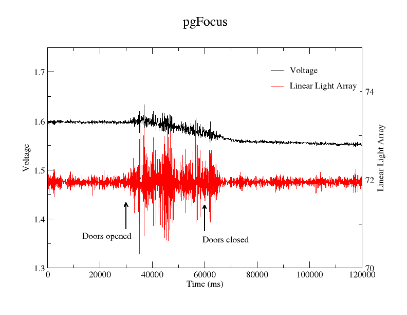
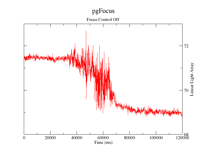
The microscope is enclosed in an environmental chamber. The doors to the chamber were opened after image 300 and closed after image 600. You will see a disturbance to the focus at both times, but focus is soon corrected within moments. The focus is disturbed due to the change in the temperature gradient across the microscope caused by the open doors.
Below is the graph of pgFocus performance from the above movie.
As you can see in the above graph, even after the doors were closed, a constant voltage adjustment had to be applied to keep focus at its original position.
Below is a graph of what happens when pgFocus isn't stabilizing focus during the same procedure.
As you can see in the bottom graph, focus position has changed even after the doors were closed due to the perturbations introduced into the microscope. The focus position may eventually correct itself once the temperature gradient returns to its original gradient.
These are severe perturbations but pgFocus is very good at automatically compensating for slow focal drift over time.
Sampling 3D Position
pgFocus is designed to sample incoming focus control signal and automatically adjust the focus control set point.
Parts
Preliminary parts list. Parts may change at any time. For a complete list, export the parts list from Eagle.
Mouser
BOM of pgFocus
BOM of TSL1401CL-Adapter
Sparkfun
| Name | Number | Reference | Notes |
|---|---|---|---|
| BNC | 2 | Sparkfun, Mouser-Plastic, Mouser-Metal, PDF | The Tyco BNC seems to match the Sparkfun |
| RGB LED | 1 | Sparkfun | Status indicator on front panel |
| JST 5 Wire | 1 | Sparkfun | TSL1401CL-Adapter and pgFocus |
Miscellaneous
| Name | Number | Reference | Notes |
|---|---|---|---|
| 808 nM laser | 1 | Thorlabs | Looking for a cheaper solution than this... |
| IR Filter or IR Transmitting Acrylic (# 1146 or 3143) | 1 | Peau ProductionsE Plastics | M12/CS Infrared Filter for M12 Shroud |
| M12 Lens Shroud | 1 | M12 Lenses | Cool because it is machined Metal |
| 4 | McMaster-Carr | Part Number 92710A211, Mounts expansion connector to back panel | |
| Panel Self-tapping Screw | 8 | McMaster-Carr | Part Number 91715A114, Mounts front and back panels to case |
| 8 | McMaster-Carr | Part Number 91249A105, Mounts sensor daughter board to back panel | |
| 4 | McMaster-Carr | Part Number 91780A740, Mounts sensor daughter board to back panel |
Thanks
pgFocus couldn't have been designed without the support from the Program in Molecular Medicine at Umass, and the following Open Software and Open Hardware communities:
